|
Home
Why?
What?
How?
Tender
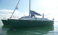
Cettia
Articles
Poems
Links
Contact
|
|||
 |
Rudders, Steerage and Propulsion
The rudders consist of 3 sheets of 12mm marine plywood laminated around the marine-grade stainless steel rudder stock.
The lamination is then profiled to give an aerofoil section, and then glassed. The rudders were constructed by
Owen in his workshop.
|
||
|
This photograph shows a close-up of the rudder stock. The way the rudderstock joins up with the tiller arm is shown in this photograph of the transom. The middle of the 3 sheets of 12mm plywood goes in between the bottom forks of the rudderstock. Top of Page 
Here is the template. The slot on the far side was cut to fit the rudder stock as tightly as possible. The rudderstock was measured using digital calipers to give an accurate measurement and the slot carefully cut to this width. Top of Page 
For the 2 outer plywood sheets housings (or dados) for the rudder stock forks have to be cut as well as the slot. A true straight edge and a router are used for both slot and housing. Top of Page 
With the rudders assembled, it is time to cut slots to the correct depth, using the profile given in the plans .... Top of Page 

The rudders are now glassed with one layer of 600g/sq m glass cloth wetted out with epoxy, followed be a coat of epoxy thickened with
colloidal silica to fill out the weave. In addition 3 strips of the same cloth are laminated around the rudder stock at the top of
the rudder, where the skeg will be when the rudder is in use, to add strength to the rudder assembly.
Top of Page 
This photograph shows the nacelle under construction. The nacelle has to support the outboard motor at the correct height above the water and
protect it from being swept away by water flowing under the bridgedeck. The transom is to be adjustable, vertically, allowing the
propeller to be raised or lowered with respect to the waterline. See the document
construction_details.pdf. for more information.
Top of Page 
When secured in the slot the rudder block provides the lower bearing for the rudder stock which, being fixed to the rudders, allows the rudders to rotate as the tillers are moved. Top of Page 
Rudders in the up position. This is achieved by releasing the downhaul and then raising the rudder using the uphaul. The downhaul needs to be tightened afterwards to stop the rudder swinging out. The uphaul and downhaul ropes are positioned in such a way as to make clambering up and down the transom as easy as possible, Top of Page 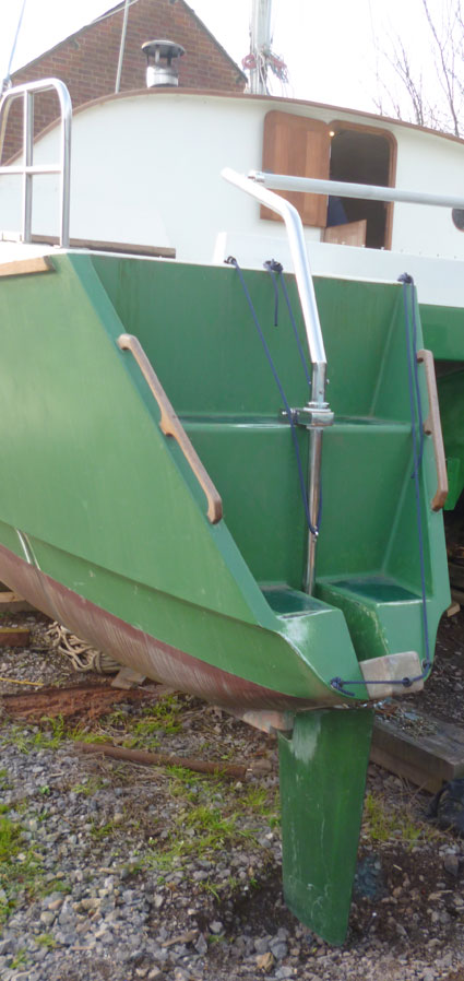
Once, motoring out of Fowey harbour in the teeth of a F6 and into a swell, I knew that if the bow blew off I did not have enough engine power to bring the boat head to the wind and waves again. On either side of the narrow harbour entrance were rocks I would have had little chance of avoiding. Fortunately, at full throttle, I had just enough power to claw my way into more open water. On another occasion, in a F6/7 and choppy seas, I had a similar experience trying to avoid being swept onto a buoy. So, I decided to add a second engine on another nacelle. Top of Page 

|

The rudder plan (provided by Richard Woods) is taped to a sheet of 12mm plywood. A bandsaw is then used to carefully cut around it. Once the first shape is cut it is used as a template to cut the other 5 identical shapes (2 rudders with a maximum thickness of 36mm) using a router. Top of Page 
The tight fit is important to make sure that the rudder stock is correctly aligned to the rudder. It has to be in the same plane as the rudder (looked at from the front or back) and at the correct angle to it (looked at from the side). Top of Page 
Once all three pieces of plywood have shaped, slotted and grooved, they are epoxied together. One can never have too many clamps!
Top of Page 
... then the rudders are planed to remove the wood down to the bottom of the slots. Top of Page 
... and again looking fore & aft, to show that the rudder stock is nicely aligned with the plane of the rudder. Top of Page 
After sanding, fairing and painting with an epoxy coat containing a green pigment. Top of Page 
The rudder block in the process of being constructed from laminated pieces of Iroko. The slot is slightly tapered and so is the rudder block which then fits snugly when the rudders are lowered from their raised position. Top of Page 
The outboard motor is in the nacelle, just to see how it fits. The string represents the waterline. It is a little higher than I expected and it will be tricky to fit the control cables. Also, I can't tilt the engine quite as much as I would like. The axis of the drive shaft is not vertical so I will have to add a wedge to the transom - doing this will lower the outboard slightly and should make it possible to achieve maximum tilt. Basically. it will work, but will need some small modifications. Top of Page 
The rudder in the down position. It is lowered on the uphaul, with gravity doing much of the work for you, and then held in position using the downhaul.
There is sufficient "slack" in the whole rudder and tiller assembly for each rudder to be raised and lowered independently.
The reason the yet-to-be-painted rudder block sticks out so much is to enable the downhaul to hold the rudder snug in the slot. The tiller bar is a GRP tube,bought 5m long and cut to size. Top of Page 
This meant sacrificing another cockpit locker and adding central controls so both engines could be operated from the same position. Another advantage of having two engines being controlled from the new steering position, on Swing Cat's centreline, was enhanced manoeuvrability, in tight spaces like marinas. Having two engines was a big improvement: I had more power, more manoeuvrability, a higher cruising speed and a bigger margin of safety since both engines would be unlikely to fail at the same time. |
||